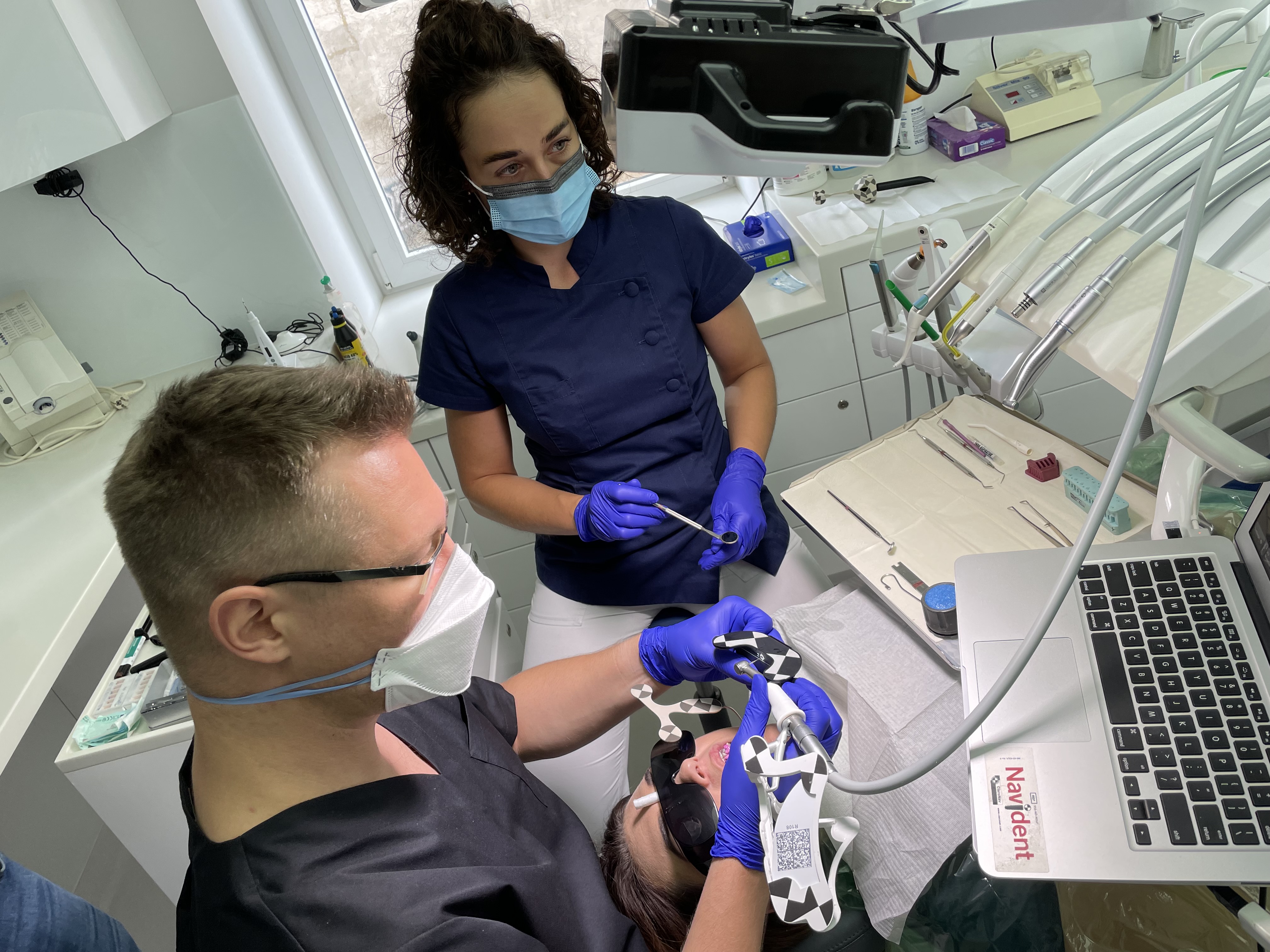
Dynamic navigation in endodontics is a relatively new technology. However, it has shown promising results and could help clinicians perform non-surgical retreatment with a better outcome. (Image: Bartlomiej Karas)
Pulp canal obliteration (PCO) is one of the complications which may occur in dental pulp after tooth trauma. It is also one of the mechanisms of pulp healing after trauma; however, pulp necrosis too may occur as a result of trauma. PCO can be recognised clinically as early as three to 12 months after trauma. PCO is an effect of the deposition of hard tissue, such as sclerotic or reparative dentine; however, the underlying mechanisms of PCO are still unclear. Oginni et al. report that partial obliteration was present in 56.9% and total obliteration in 43.1% of 276 cases of teeth after trauma, and they suspect that the mechanism of formation of obliteration is related to damage to the neurovascular supply.
The types of injuries mostly responsible for PCO have also been investigated. It was revealed that luxation, subluxation, intrusion and concussion are the most frequent causes of trauma. In the case of concussion, teeth with developing apices have a better prognosis and a lower likelihood of developing PCO.
Jacobsen and Kerekes report that, although PCO necrosis and periapical disease are rare, they can occur after many years after the trauma. Bastos and Cortes emphasise that crown discoloration can be present in many cases and can be a first visible factor of PCO. Usually, the colour changes to dark yellow or even grey.
Management of PCO owing to a lack of patency can be very challenging for clinicians. Creating a proper access cavity (one that will not sacrifice too much tooth structure) and locating the root canal orifice in the calcified tooth requires experience and additional equipment, like a dental operating microscope. According to Carvalho and Zuolo, using the dental operating microscope increases the probability of finding all the orifices located in the pulp chamber floor. Boveda and Kishen state that creating a constricted access cavity should be very valuable in terms of a long-term prognosis, but can require an additional diagnostic protocol, for example capturing a CBCT scan before the treatment.
Dynamic navigation
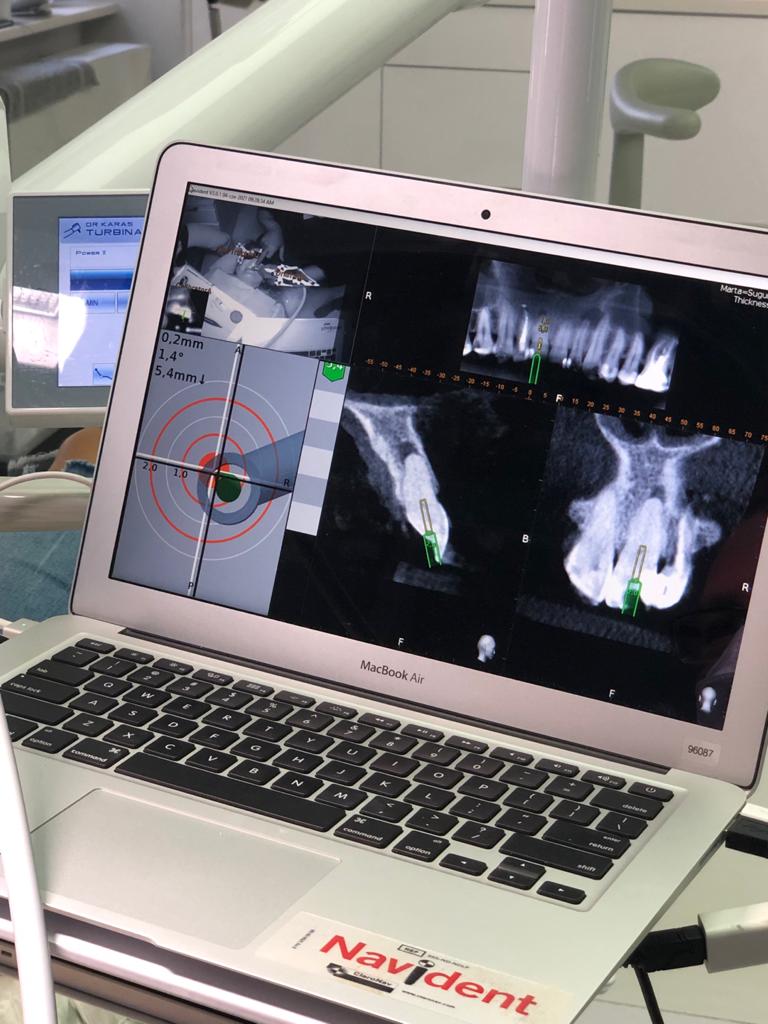
Nowadays, thanks to the development of modern technologies, it has become possible to perform treatment more conservatively and more predictably. The Navident dynamic navigation system (ClaroNav) is to a clinician what a GPS is to a driver. Navident uses a stereoscopic camera and marker (or reference) spheres so that the camera can track the movement of the operator. Also the system requires a CBCT scan of the patient and a digital guide, which is designed in the Navident software. After designing the guide, the clinician needs to register the patient’s teeth to calibrate the CBCT scan with a special tool (the wand). After registration of the patient’s teeth, the clinician needs to calibrate the drill and the handpiece with dedicated markers. With the combination of the prepared guide, tracking markers and dynamic tracking of the camera, the dentist can see the actual position of the drill and its angulation with a lag of 0.3–0.5 seconds on the computer screen. According to available data, the accuracy of the equipment is 0.1 mm and 1°, which is significantly better than CAD/CAM-fabricated guides for endodontic treatment. It must be considered that the accuracy of the procedure may differ depending on the clinician.
Case 1
A 36-year-old female patient came to the dental office with discoloration and pain of the maxillary right first incisor (Fig. 1). In the medical history taking, she reported a trauma approximately 15 years earlier. During the radiographic examination in the office of her general dentist, PCO was revealed. She was referred for a CBCT scan and endodontic treatment.
During the consultation, the CBCT scan was performed with the 9000 C 3D with a voxel size of 0.1 mm (Carestream). The CBCT scan revealed a highly calcified pulp chamber and an almost invisible trace of the root canal (Fig. 2). The patient was informed about the new, beneficial technology which can help to preserve additional tooth structure during treatment.
Fig. 1: Intra-oral view of the initial situation. Visible discoloration of the right central incisor.
Figs. 2a & b: CBCT scan, sagittal (a) and coronal planes (b). Visible pulp canal obliteration and periapical lesion.
Figs. 3a–c: Planning of the virtual guide in Navident software (ClaroNav). The axis and depth of the preparation are shown.
Fig. 4: Calibration of the Navident device. The tracers and camera are shown.
Before the treatment, the CBCT scan was uploaded to the software and the virtual guide was planned (Fig. 3). This is one of the most important parts of the protocol because during the treatment the Navident software tracks the handpiece and shows the correlation between the clinician’s work and the already planned guide. If the depth or direction is missed on the guide, there is a very high risk of root perforation.
During the clinical procedure, the jaw tracker was placed on the patient’s teeth and fixed with impression material. Registration of the patient’s tooth position and calibration of the CBCT scan was performed with the help of the wand tool. The drill tag was attached to the handpiece, and the calibration of the handpiece and drill was performed with the calibration tool (Fig. 4). After all the registration and calibration procedures, the patient, tooth and guide were prepared for the access cavity creation. The access cavity was created with the EndoGuide bur (SS White Dental) with the aid of the Navident software. The greatest challenge of the procedure for the clinician is to work simultaneously with the fast-speed handpiece in the tooth and trace the position and angulation of the drill on the computer screen, potentially leading to trouble with coordination in the first procedures (Fig. 5).
Fig. 5: Intra-op view of the software.
After reaching the depth of drilling on the prepared guide, another CBCT scan was performed to check the accuracy of the access cavity (Fig. 6). According to the image, the angulation of the access cavity had changed slightly to the palatal side and the root canal was reached with the #10 K-file (Kendo, VDW; Fig. 7). Shaping of the root canal was performed with Endostar E3 Azure (Poldent) up to size 30/0.04. After the shaping protocol, the size of the root canal orifice was checked with the #80 hand plugger, and it was indicated that the size was larger than #80 but smaller than #100 (Fig. 8). The irrigation protocol was performed with 5.25% sodium hypochlorite and 40.0% citric acid. Both solutions were activated with Eddy sonic tips (VDW), and sodium hypochlorite was additionally activated with Elements Free (Kerr) for intra-canal heating. The canal was dried with paper points (Fig. 9) and obturated with warm gutta-percha using the continuous wave technique, and a control radiograph was performed (Fig. 10). The access cavity was sealed with a composite material, and another radiograph was performed (Fig. 11).
The recall appointment took place four months after treatment. Healing of the periapical tissue was observed. Despite the limitations of the CBCT imaging related to the voxel size (0.1 mm), the size of the access cavity was found to be 1.1 mm ± 0.2 mm, confirming the measurement performed during treatment (Fig. 12). Moreover, we could also confirm that the access cavity and the root canal preparation had the same angulation, parallel to the long axis of the root, and remained in the centre of the root (Fig. 13).
Figs. 6a & b: First stage of the access cavity creation (a). CBCT check, sagittal plane (b). The axis of the access cavity was visible.
Figs. 7a & b: Hand file scouting of the canal orifice.
Figs. 8a & b: Final preparation (a). The size of the access cavity and of the root canal orifice was checked with the #80 hand plugger (b).
Figs. 9a & b: Drying the canal before obturation.
Figs. 10a & b: Obturation with gutta-percha (a) and the control radiograph (b).
Figs. 11a & b: Occlusal check (a) and the control radiograph of the composite seal (b).
Fig. 12: CBCT check, sagittal plane. Measurement of the root thickness conrmed the size of the preparation. Healing of the periapical tissue was observed.
Fig. 13: CBCT check, sagittal plane. The long axis of the root and the axis of the access cavity and root canal preparation were visible.
Case 2
A 30-year-old female patient presented to the dental clinic complaining of constant pain of the left central incisor. Moreover, the patient was unhappy with the aesthetics of both incisors and had a history of trauma (Fig. 14). CBCT examination was performed with the 9000 C 3D (Fig. 15). The CBCT scan revealed a periapical lesion around the left central incisor and PCO for 12 mm from the incisal edge. The root of the left incisor was approximately 5 mm shorter than the root of the right incisor, which could indicate apical inflammatory root resorption. Moreover, PCO was present in the right central incisor up to 12 mm from the incisal edge, and an irregular shadow in the central area of the root was present. This image could indicate internal resorption. There was no lesion in the periapical area. In both teeth, the size of the canals in the periapical area were narrower than the typical size of the canals in the central incisors.
Before the treatment, the CBCT scan was uploaded to the software and the virtual guide was planned (Figs. 16 & 17). All the registration and calibration procedures were performed in the same manner as the previous case.
Fig. 14: Intra-oral view of the initial situation. Visible discoloration of the right central incisor.
Figs. 15a–c: CBCT scan, sagittal (a & b) and coronal planes (c). Pulp canal obliteration was visible in both teeth, and a periapical lesion was present around the left incisor. Internal resorption in the right incisor was suspected.
Figs. 16a–c: Planning of the virtual guide for the right incisor. The axis and depth of the preparation are shown.
Figs. 17a–c: Planning of the virtual guide for the left incisor. The axis and depth of the preparation are shown.
The access cavity was performed with the EndoGuide bur with the aid of the software. After reaching the depth of drilling on the prepared guide, another CBCT scan was performed to check the accuracy of the access cavity (Fig. 18). The CBCT scan revealed that the angulation of the access cavity was suitable but that the depth was insufficient. The EndoGuide drill and Navident were used one more time to reshape the access cavity. After gaining patency in the canal, the #10 K-file was used to establish the working length. The canal in the right incisor was shaped with Endostar E3 Azure up to size 40/0.04, and the canal in the left incisor was shaped up to size 45/0.04. In both canals, the irrigation protocol was performed with 5.25% sodium hypochlorite and 40.0% citric acid. Both solutions were activated with Eddy sonic tips, and sodium hypochlorite was additionally activated with Elements Free for intra-canal heating. The canals were dried with paper points (Fig. 19) and obturated with warm gutta-percha using the continuous wave technique, and a control radiograph was performed (Fig. 20). Finally, the composite sealing was performed and the occlusal check was done (Fig. 21).
Figs. 18a & b: CBCT check, sagittal plane. The axis of the access cavity was visible for both teeth.
Figs. 19a & b: Drying the canal before obturation (a). The nal shape of the access cavity (b).
Figs. 20a–c: Obturation with gutta-percha (a & b) and the control radiograph (c).
Figs. 21a & b: Occlusal check (a) and the control radiograph of the composite seal (b).
Conclusion
Although dynamic navigation in endodontics is a very new and uncharted technology, the three teeth with massive PCO in these case reports proved that it offers very promising utility for endodontists. This technology requires further investigation, but it appears that it could help many clinicians to treat teeth with PCO and perform non-surgical retreatment with a better outcome. Moreover, using this technology in preparing constricted access cavities appears to be very promising in terms of the survival of the treated teeth thanks to preserved tooth structure such as peri-cervical dentine. Therefore, digital solutions like Navident should be used more often in endodontics to gather more data and create a new standard for treating teeth with PCO in the future.
AUCKLAND, New Zealand: Social media increasingly shapes ideas about what constitutes a healthy, attractive or socially acceptable smile. Researchers from ...
TOKYO, Japan: Despite facing increasingly tight schedules and growing operational and financial pressures, today’s dental practitioners are expected to ...
AJMAN, UAE: Artificial intelligence (AI) is reshaping dental education by changing how students learn, educators teach and institutions prepare graduates ...

 Brazil / Brasil
 Canada / Canada
 Latin America / Latinoamérica
 USA / USA
 Austria / Österreich
 Bosnia and Herzegovina / Босна и Херцеговина
 Bulgaria / България
 Croatia / Hrvatska
 Czech Republic & Slovakia / Česká republika & Slovensko
 France / France
 Germany / Deutschland
 Greece / ΕΛΛΑΔΑ
 Hungary / Hungary
 Italy / Italia
 Netherlands / Nederland
 Nordic / Nordic
 Poland / Polska
 Portugal / Portugal
 Romania & Moldova / România & Moldova
 Slovenia / Slovenija
 Serbia & Montenegro / Србија и Црна Гора
 Spain / España
 Switzerland / Schweiz
 Turkey / Türkiye
 UK & Ireland / UK & Ireland
 China / 中国
 India / भारत गणराज्य
 Pakistan / Pākistān
 Vietnam / Việt Nam
 ASEAN / ASEAN
 Israel / מְדִינַת יִשְׂרָאֵל
 Algeria, Morocco & Tunisia / الجزائر والمغرب وتونس
 Middle East / Middle East

 Dr. Cameron Shahbazian DMD MBARegister now1CELive webinar
 Dr. Bruce McFarlane Certified Specialist in Orthodontics Fellow: Royal College of Dentists of Canada Diplomate: American Board of OrthodonticsLive webinar


 Prof. Dr. Wael Att, Dr. Andrea Laureti ITI Scholar Michigan, Dr. Acela MartinezLive webinar
 Cat EdneyRegister now1CE


 and coronal planes (b). Visible pulp canal obliteration and periapical lesion.")
. The axis and depth of the preparation are shown.")
. CBCT check, sagittal plane (b). The axis of the access cavity was visible.")

. The size of the access cavity and of the root canal orifice was checked with the #80 hand plugger (b).")

 and the control radiograph (b).")
 and the control radiograph of the composite seal (b).")


 and coronal planes (c). Pulp canal obliteration was visible in both teeth, and a periapical lesion was present around the left incisor. Internal resorption in the right incisor was suspected.")


. The nal shape of the access cavity (b).")
 and the control radiograph (c).")
 and the control radiograph of the composite seal (b).")


To post a reply please login or register