Search Dental Tribune

Fig. 1a: Initial clinical situation. Large composite restoration showing marginal porosities. (All images: Dr Jotautas Kaktys)

Mon. 24. August 2026

save

Restoration of an endodontically treated tooth can be quite challenging, mainly because so many decisions need to be made. The clinician must evaluate the structural condition of the tooth and decide whether a direct or indirect restoration should be selected, which cusps should be overlaid and which should be preserved, and whether post or fibre placement is required. Should the clinician decide on an indirect approach, he or she would then need to choose from the wide range of restorative materials and restoration designs.

At our &SMILE clinic in Kaunas in Lithuania, the main goal is always to preserve as much natural tooth structure as possible without compromising the longevity of the restoration. Consequently, we opt for the least invasive clinically sound approach, using materials that mimic the mechanical and optical properties of the natural dentition. In this context, hybrid ceramics, such as KATANA AVENCIA Block 2 (Kuraray Noritake Dental), are often a valuable choice. The following case demonstrates a biomimetic approach in a situation that required endodontic retreatment followed by indirect restoration of a tooth that had previously been restored with composite.

Case presentation

The patient presented for a routine check-up. A large composite restoration on tooth #16 attracted our attention because it appeared to be structurally compromised. Clinical examination revealed occlusal porosities along the restoration margin, as well as cracked and chipped areas (Fig. 1a). The buccal margin was stained and leaking (Fig. 1b), and on the palatal surface, microcracks in the tooth structure were visible (Fig. 1c).

Fig. 1b: Initial clinical situation. Large composite restoration showing a stained, leaking buccal margin.

Fig. 1b: Initial clinical situation. Large composite restoration showing a stained, leaking buccal margin.

Fig. 1c: Initial clinical situation. Large composite restoration showing a microcracks in the tooth structure on the palatal surface.

Fig. 1c: Initial clinical situation. Large composite restoration showing a microcracks in the tooth structure on the palatal surface.

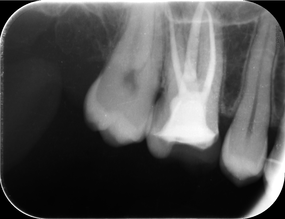
Since the tooth had been endodontically treated elsewhere several years earlier, a radiograph was taken (Fig. 2). It revealed that the canals had not been filled to the apices. However, because the patient showed no symptoms, the decision was made to proceed with an indirect restoration without endodontic retreatment.

The reasons for choosing an indirect restoration included the large size of the composite restoration and the compromised condition of the surrounding tooth structure. Compared with a direct restoration, an adhesively cemented indirect restoration offers the additional benefits of virtually no polymerisation shrinkage, minimal stress on the already compromised tooth structure and improved mechanical properties.

The tooth shade was determined immediately. The adjacent premolar matched Shade A3 of the VITA classical A1–D4 shade guide in the middle third, while the occlusal third showed whitish spots and appeared brighter, closer to Shade A2 (Fig. 3). This information was recorded for the dental laboratory.

Fig. 2: Initial radiograph showing radiolucent areas in the apical region, indicating incomplete root canal filling.

Fig. 2: Initial radiograph showing radiolucent areas in the apical region, indicating incomplete root canal filling.

Fig. 3: Selection of Shade A2 of the VITA classical A1–D4 shade guide based on the shade of the surrounding tooth structure.

Fig. 3: Selection of Shade A2 of the VITA classical A1–D4 shade guide based on the shade of the surrounding tooth structure.

Reassessment and treatment planning

After dental dam placement, minimally invasive tooth preparation was carried out, reducing parts of the composite restoration as well as areas of tooth structure that were not structurally sound because of cracks and insufficient thickness (Fig. 4). Wherever mostly brittle enamel remains, cuspal coverage is generally preferable, as it helps reinforce and protect weakened cusps. The distopalatal cusp was preserved because it had adequate dentine support and no cracks underneath.

Once the onlay preparation had been completed, gaps around the composite–tooth interface became visible below the remaining composite (Fig. 5). We therefore decided to remove all the composite and prepare the access cavity, exposing the threaded metal post (Fig. 6). The post was further exposed using small burs, ultrasonic tips and air abrasion with 53 μm alumina powder (AquaCare Twin, Velopex International) and then removed (Fig. 7a). The cleaned cavity revealed an untreated second mesiobuccal canal, and the treated canals also appeared to have been insufficiently cleaned (Fig. 7b).

Fig. 4: Dental dam placed and secured with a clamp.

Fig. 4: Dental dam placed and secured with a clamp.

Fig. 5: Completed onlay preparation. Gaps and white lines beneath the composite restoration indicated debonding of the composite.

Fig. 5: Completed onlay preparation. Gaps and white lines beneath the composite restoration indicated debonding of the composite.

Fig. 6: Threaded metal post exposed using small burs, air abrasion and ultrasonic tips.

Fig. 6: Threaded metal post exposed using small burs, air abrasion and ultrasonic tips.

Figs. 7a & b: Post after removal (a). Cleaned cavity revealing an untreated second mesiobuccal canal and treated canals that appeared to have been insufficiently cleaned (b).

Figs. 7a & b: Post after removal (a). Cleaned cavity revealing an untreated second mesiobuccal canal and treated canals that appeared to have been insufficiently cleaned (b).

This raised concern about inadequate instrumentation, and the findings were confirmed radiographically (Fig. 8). The risk of future endodontic complications thus appeared higher than previously estimated, even in the absence of symptoms. Consequently, the treatment plan was changed to include endodontic retreatment followed by restorative treatment. The build-up and placement of the restoration after endodontic treatment were planned for the same visit because this would be more efficient for both clinician and patient.

Sealing and preparation prior to endodontic retreatment

During endodontic treatment, chemicals such as sodium hypochlorite and EDTA are typically used for irrigation and root canal disinfection. Unfortunately, these chemicals have been shown to negatively affect resin–dentine bond strength.1

The technique referred to as “immediate pre-endodontic dentine sealing” has proved effective in optimising bonding conditions.1 In this approach, described earlier in the literature as “immediate access cavity sealing”,2 an adhesive and a flowable composite are applied to freshly cut dentine before exposure to chemical substances. The established seal protects the dentine from contamination by irrigants and temporary cements. It also allows time for bond maturation, enabling the adhesive to reach its full bonding potential and better withstand composite polymerisation shrinkage stresses during restoration of the access cavity. This has been associated with greater continuity of the hybrid layer and fewer interfacial gaps.2

In the present case, air abrasion was performed to clean the surfaces and reduce the smear layer for better adhesive penetration. The dentine was then sealed with CLEARFIL SE Protect, a two-step self-etch adhesive system with antibacterial effects (Figs. 9a & b), in combination with the high-flowability version of CLEARFIL MAJESTY ES Flow (both Kuraray Noritake Dental). The primer was applied to all the dentine, the amelodentinal junction and a small amount of the enamel and left to react for at least 20 seconds before a thin layer of the adhesive was carefully applied. Instead of being air thinned, the excess was wicked away with a clean brush to avoid both pooling of the adhesive in deeper areas and excessive thinning elsewhere, which could have compromised polymerisation through oxygen inhibition.

Fig. 8: Second radiograph taken for reassessment of the initial situation, confirming the inadequate quality of the previous root canal treatment.

Fig. 8: Second radiograph taken for reassessment of the initial situation, confirming the inadequate quality of the previous root canal treatment.

Fig. 9a & b: Immediate dentine sealing before endodontic treatment using CLEARFIL SE Protect Primer (a), followed by CLEARFIL SE Protect Bond (b).

Fig. 9a & b: Immediate dentine sealing before endodontic treatment using CLEARFIL SE Protect Primer (a), followed by CLEARFIL SE Protect Bond (b).

Fig. 9a & b: Immediate dentine sealing before endodontic treatment using CLEARFIL SE Protect Primer (a), followed by CLEARFIL SE Protect Bond (b).

Fig. 9a & b: Immediate dentine sealing before endodontic treatment using CLEARFIL SE Protect Primer (a), followed by CLEARFIL SE Protect Bond (b).

A 0.5 mm layer of the selected flowable composite was then applied and light-polymerised. To block the small canal openings, a light-polymerising liquid dental dam was applied. Owing to its opaque white colour, it is easy for the endodontist to identify and remove. The larger canal opening was blocked with PTFE tape and covered with the flowable composite (Fig. 10).

To enable restoration of the access cavity and placement of the definitive indirect restoration in a single appointment, more than two-thirds of the surface that would later receive the onlay was built up, leaving only a small portion of the cavity open for the endodontist. In this way, it was possible to take the digital impression and thus generate sufficient information for the design and fabrication of the onlay without compromising its fit. To create the bonded composite base for the onlay, the radiopaque hybrid composite CLEARFIL AP-X was selected because of its excellent mechanical properties, including high strength (Fig. 11). The onlay preparation was then completed (Fig. 12), and air abrasion with 30 μm alumina powder was performed to clean the enamel margins and smooth the preparation surface (Fig. 13).

The final preparation design included the access cavity and a sufficiently large surface to allow accurate design and seating of the planned restoration (Fig. 14). The access cavity was closed with PTFE tape and the liquid dental dam (Figs. 15a & b), and a soft composite (ENA Soft, Micerium) was placed as a temporary restoration to keep the tooth stable until placement of the definitive restoration (Fig. 16). A digital impression was taken, and the patient was referred to an endodontist for retreatment.

Fig. 10: Cavity sealed with flowable composite and canal openings blocked with the liquid dental dam and PTFE tape.

Fig. 10: Cavity sealed with flowable composite and canal openings blocked with the liquid dental dam and PTFE tape.

Fig. 11: Optimal cavity design after bonding of the composite base for the onlay, leaving only the access cavity open for the endodontist.

Fig. 11: Optimal cavity design after bonding of the composite base for the onlay, leaving only the access cavity open for the endodontist.

Fig. 12: Finishing the onlay preparation.

Fig. 12: Finishing the onlay preparation.

Fig. 13: Air abrasion to clean the enamel margins and smooth the preparation surface.

Fig. 13: Air abrasion to clean the enamel margins and smooth the preparation surface.

Fig. 14: Final preparation design.

Fig. 14: Final preparation design.

Fig. 15a: Access cavity closed with PTFE tape.

Fig. 15a: Access cavity closed with PTFE tape.

Fig. 15b: Access cavity closed with the liquid dental dam.

Fig. 15b: Access cavity closed with the liquid dental dam.

Fig. 16: White liquid dental dam showing through the temporary restoration, serving as a useful guide for the endodontist to help preserve the shape of the composite base.

Fig. 16: White liquid dental dam showing through the temporary restoration, serving as a useful guide for the endodontist to help preserve the shape of the composite base.

CAD/CAM material selection and restoration design

We selected a restorative material that was fast and easy to process, financially accessible, and capable of offering pleasing optical and mechanical properties for reliable long-term performance: KATANA AVENCIA Block 2. It is manufactured by pressing ultra-fine filler particles into high-density blocks, uniformly impregnating the filler structure with resin monomer and then heat-polymerising the resin. According to the manufacturer, this production process results in particularly high wear resistance and restorations that are highly polishable and gentle on the opposing dentition.

KATANA AVENCIA Block 2 is offered in a multilayered version with natural colour gradation and in a high-translucency version designed for inlays and onlays requiring seamless optical integration. To evaluate the optical properties of the multilayered version, we decided to mill the restoration from a low-translucency block in Shade A2 as well as the multilayered version of KATANA AVENCIA Block 2 in the same shade, alongside comparable materials from other manufacturers.

For this purpose, the intra-oral scans taken after tooth preparation were exported into DentalCAD software (exocad; Fig. 17a). The onlay was designed in full contour, using a copy of the contralateral molar as a reference (Figs. 17b & c). The restoration was then milled from several materials. Afterwards, the milling sprues were removed and the surfaces polished with diamond burs and TWIST DIA for Composite (Kuraray Noritake Dental).

Definitive build-up and restoration placement

During the second appointment, the build-up and restoration were carried out. The temporary composite was removed quickly to avoid dehydration of the teeth and allow realistic evaluation of the onlays’ aesthetic properties. All the restorations were then tried in with glycerine gel and their appearance compared. The multilayered version of KATANA AVENCIA Block 2 in Shade A2 (Fig. 18a) produced an aesthetic result and blended in nicely with the surrounding tooth structure (Figs. 18b & c), and it was therefore selected for the definitive restoration.

The composite and the access cavity were then cleaned, and the composite was reactivated. To achieve this, the surface was air abraded with 30 μm silica-coated alumina powder (Fig. 19). This exposed remaining reactive sites in the resin matrix and produced a clean, roughened, silica-coated surface to support micromechanical and chemical bonding of the restorative material and the definitive restoration.


CAD/CAM material selection and restoration design

We selected a restorative material that was fast and easy to process, financially accessible, and capable of offering pleasing optical and mechanical properties for reliable long-term performance: KATANA AVENCIA Block 2. It is manufactured by pressing ultra-fine filler particles into high-density blocks, uniformly impregnating the filler structure with resin monomer and then heat-polymerising the resin. According to the manufacturer, this production process results in particularly high wear resistance and restorations that are highly polishable and gentle on the opposing dentition.

KATANA AVENCIA Block 2 is offered in a multilayered version with natural colour gradation and in a high-translucency version designed for inlays and onlays requiring seamless optical integration. To evaluate the optical properties of the multilayered version, we decided to mill the restoration from a low-translucency block in Shade A2 as well as the multilayered version of KATANA AVENCIA Block 2 in the same shade, alongside comparable materials from other manufacturers.

For this purpose, the intra-oral scans taken after tooth preparation were exported into DentalCAD software (exocad; Fig. 17a). The onlay was designed in full contour, using a copy of the contralateral molar as a reference (Figs. 17b & c). The restoration was then milled from several materials. Afterwards, the milling sprues were removed and the surfaces polished with diamond burs and TWIST DIA for Composite (Kuraray Noritake Dental).

Definitive build-up and restoration placement

During the second appointment, the build-up and restoration were carried out. The temporary composite was removed quickly to avoid dehydration of the teeth and allow realistic evaluation of the onlays’ aesthetic properties. All the restorations were then tried in with glycerine gel and their appearance compared. The multilayered version of KATANA AVENCIA Block 2 in Shade A2 (Fig. 18a) produced an aesthetic result and blended in nicely with the surrounding tooth structure (Figs. 18b & c), and it was therefore selected for the definitive restoration.

The composite and the access cavity were then cleaned, and the composite was reactivated. To achieve this, the surface was air abraded with 30 μm silica-coated alumina powder (Fig. 19). This exposed remaining reactive sites in the resin matrix and produced a clean, roughened, silica-coated surface to support micromechanical and chemical bonding of the restorative material and the definitive restoration.

After verification of the onlay fit in a dry try-in, selective enamel etching was carried out with phosphoric acid (Fig. 20). CLEARFIL Universal Bond Quick (Kuraray Noritake Dental) was then applied to the entire tooth surface, including the root canals. A layer of flowable composite (CLEARFIL MAJESTY ES Flow High) was placed for resin coating of the roots canals (Fig. 21), and a short fibre-reinforced resin-based composite core (everX Flow, Dentin shade, and everX Posterior, GC) was placed to increase the tooth’s fracture resistance, and the same composite was built up in layers to improve the Krenchel reinforcement factor (Figs. 22a & b). The covering layer was completed using CLEARFIL AP-X, which was modelled slightly below the final level to avoid interference with the onlay placement, and light-polymerised (Fig. 23). The fit of the onlay was then checked before cementation.

Fig. 19: After the silica-coating treatment performed to optimise bonding conditions.

Fig. 19: After the silica-coating treatment performed to optimise bonding conditions.

Fig. 20: Selective etching of the enamel margins with phosphoric acid.

Fig. 20: Selective etching of the enamel margins with phosphoric acid.

Fig. 21: After application of a universal adhesive to the entire surface and coating of the root canals with flowable composite.

Fig. 21: After application of a universal adhesive to the entire surface and coating of the root canals with flowable composite.

Fig. 22a: Placement of the short fibre-reinforced composite core.

Fig. 22a: Placement of the short fibre-reinforced composite core.

Fig. 22b: Subsequent layering with the same resin-based composite.

Fig. 22b: Subsequent layering with the same resin-based composite.

Fig. 23: Core build-up completed with a radiopaque composite.

Fig. 23: Core build-up completed with a radiopaque composite.

To provide optimal bonding conditions, the intaglio surface of the onlay was air abraded with 30 μm silica-coated alumina powder (Fig. 24). This cleaned and roughened the surface, deposited a silica layer and exposed unpolymerised monomer sites. Afterwards, the intaglio surface of the onlay was treated with CLEARFIL CERAMIC PRIMER PLUS (Kuraray Noritake Dental), which contains silane and the original MDP monomer needed to establish a chemical bond between the restoration and the resin (Fig. 25).

Fig. 24: Air abrasion of the intaglio surface of the restoration.

Fig. 24: Air abrasion of the intaglio surface of the restoration.

Fig. 25: Priming of the restoration with CLEARFIL CERAMIC PRIMER PLUS.

Fig. 25: Priming of the restoration with CLEARFIL CERAMIC PRIMER PLUS.

The adjacent teeth were then isolated with PTFE tape, and PANAVIA Veneer LC (Kuraray Noritake Dental) was applied. This light-polymerising resin cement is designed for use with the primer and adhesive used in this case. Because it is purely light-polymerised, it offers a longer working time than dual-polymerising cements, making the procedure less stressful, and it has excellent mechanical and wear properties. Owing to the need for light to pass through the material to achieve complete polymerisation, however, the thickness of restorations placed with this resin cement should not exceed 2 mm.

Fig. 32: Final radiograph.

Fig. 32: Final radiograph.

After careful seating of the restoration (Fig. 26), excess material was removed with brushes and a micro-brush before the initial polymerisation. A layer of glycerine gel was then applied to the restoration margins to avoid formation of an oxygen inhibition layer during polymerisation (Fig. 27). The light polymerisation was then carried out carefully from all sides of the restoration (Fig. 28). Excess material was removed and the margins polished (Figs. 29a & b; 30).

Two weeks later, the restoration showed good optical integration and healthy soft-tissue conditions (Fig. 31). A final radiograph confirmed the success of the endodontic and restorative treatment (Fig. 32). At the nine-month recall, the restoration remained in excellent condition and integrated very well optically (Figs. 33a–c).

Conclusion

As manufacturers continue to improve dental materials, it becomes easier to restore teeth in a biomimetic way. Using high-performance instruments, adhesives, composites, resin cements and CAD/CAM materials such as hybrid ceramics, clinicians and technicians are able to substantially extend the lifespan of many non-vital teeth while gently restoring their aesthetics and function. These materials support standardised, streamlined procedures and simplify aesthetic outcomes through innovative properties such as multilayered colour structures, allowing more time to focus on what matters most: patients’ oral health and satisfaction.

Fig. 33a: Restoration at the nine-month recall, showing stain-free margins and smooth surfaces owing to excellent polish retention, occlusal view.

Fig. 33a: Restoration at the nine-month recall, showing stain-free margins and smooth surfaces owing to excellent polish retention, occlusal view.

Fig. 33b: Buccal view.

Fig. 33b: Buccal view.

Fig. 33c: Oblique occlusal view.

Fig. 33c: Oblique occlusal view.

Acknowledgement
Special thanks to dental technician Tautvilas Kaktys and the RiCreo dental laboratory for their outstanding laboratory support and craftsmanship.

Editorial note:

References

  1. Carvalho MA, Lazari-Carvalho PC, Maffra PE, Izelli TF, Gresnigt M, Estrela C, Magne P. Immediate pre-endodontic dentin sealing (IPDS) improves resin-dentin bond strength. J Esthet Restor Dent. 2025 Jan;37(1):39–47. doi: 10.1111/jerd.13395.
  2. De Rose L, Krejci I, Bortolotto T. Immediate endodontic access cavity sealing: fundamentals of a new restorative technique. Odontology. 2015 Sep;103(3):280–5. doi: 10.1007/s10266-014-0174-1.

This article was published in CAD/CAM—international magazine of dental laboratories vol. 17. issue 1/2026.

Topics:
Tags:
To post a reply please login or register
advertisement
advertisement